

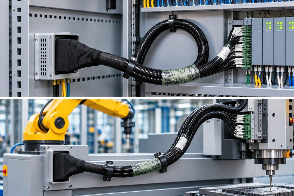
The module’s data acquisition harness is located between the cell’s measurement point and the testing equipment. Loose connections, mismatched wiring sequences, or incompatible equipment interfaces can all cause voltage data jumps, gaps, or channel inconsistencies. During troubleshooting, the harness should first be considered as part of the signal chain before determining whether the problem originates from the cell or the instrument.
Why does the module’s data acquisition harness affect voltage detection?
Signal path from individual measuring point to testing equipment
The voltage at each individual measurement point must pass through terminals, wires, connectors, and equipment channels before entering the BMS or testing system. Any change in the contact resistance of any connection point will cause a momentary shift in the acquired value, especially after vibration, plugging/unplugging, or maintenance.
The significance of connection stability and line sequence consistency
The data acquisition harness must not only be conductive, but also ensure that the channel sequence is consistent with the battery module definition. When the wiring sequence is misaligned, the data may appear to have a value, but the cell number does not correspond to the actual location. The BMS may then make protection or equalization decisions based on the incorrect location.
How to troubleshoot common anomalies starting with the wiring harness
Voltage jumps and intermittent loss
If a channel repeatedly jumps in readings while stationary, or if slight movement of the wiring harness causes a change in readings, check the terminal crimping, connector locking, and wiring harness stress. If multiple adjacent channels are missing simultaneously, also inspect the common connector, adapter board, and device-side interface.
Channel misalignment and abnormal line sequence
Checking the channel numbers, module test points, and device ports one by one is a direct way to rule out incorrect connections. Don’t just look at whether the total voltage is reasonable, because the sum after misalignment may still be close to normal. The real anomaly will be revealed in the individual unit sequencing, temperature correlation, or equalization operation.
The instrument is working properly, but the data is still inconsistent.
Cross-testing can be performed using modules in known states or stable reference channels. If the instrument self-test is normal, but the anomaly consistently moves with a particular harness or connector, the fault location should return to the harness itself, rather than repeatedly changing software parameters.
What needs to be checked when selecting a module acquisition harness?
Connector, channel and device interface adapters
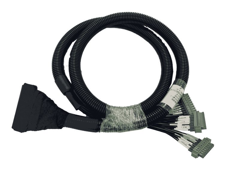
First, confirm the number of test points for the battery module, connector series, locking method, pin definitions, and device interface, then determine the wiring harness channel layout. For EOL or dedicated test benches, the fixture positioning and error-proofing structure should also be checked to avoid situations where the device can be plugged in but cannot collect data correctly.
Line length, protective structure and usage environment
The cable length and routing path should meet the operational requirements of the workstation while avoiding excessive bending, pulling, or friction with high-temperature edges. When the cable needs to be used in environments with movement, vibration, or repeated insertion and removal, the sheath, branch fixing, and terminal protection should be included in the design review.
Standard configuration and customization boundaries
Guheng Energy provides equalization harnesses, module power acquisition harnesses, module power harnesses, low-voltage communication harnesses, and high-voltage test harnesses, and can customize them according to equipment matching, automotive testing, and other applications. Due to significant differences in interfaces between different devices, complete interface and channel definitions should be provided before customization, rather than simply describing “battery harness”.
How to connect wire harnesses to different test procedures
Equalization and module charge/discharge maintenance
When connecting wire harnesses to equalizers or module chargers/dischargers, the key points are channel correspondence, polarity, and connection sequence. A stable acquisition path allows equalization actions to correspond to individual cell voltage changes and reduces repeated shutdowns caused by loose connections.
Battery pack charge/discharge and EOL check
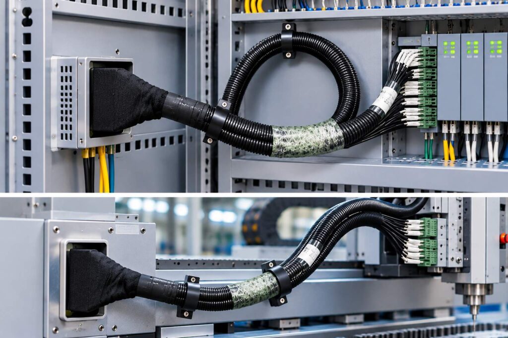
Battery pack chargers and end-of-life (EOL) devices typically require more explicit interface partitioning and error-proofing management. Separating and labeling the acquisition harness, power harness, and low-voltage communication harness according to their functions helps reduce misconnections and allows anomalies to be traced back to the specific link more quickly.
After-sales retesting and batch application
After-sales on-site inspections focus on quick replacement, easy connection, and reproducible results; batch applications prioritize batch consistency and inspection records. Incorporating wiring harnesses into routine visual inspections, channel verification, and plug-in life observation can expose many intermittent faults in advance.
The Applicability Value of Solid Energy Solutions
Equipment matching and customization capabilities
Guheng Energy possesses capabilities in wire harness R&D, processing, and sales. Its products can be used with equalizers, module charge/dischargers, battery pack charge/dischargers, and end-of-life (EOL) equipment. When selecting a wire harness, you can understand its application scope by collecting data on the module , and then confirm the final solution by referring to the equipment interface diagram, channel table, and on-site operation.
Incorporate wiring harnesses into routine inspections and quality control.
Wiring harnesses are not disposable consumables, but rather components that continuously withstand insertion, removal, bending, and environmental changes within the testing system. Through connector locking verification, channel continuity checks, outer sheath inspection, and abnormal data documentation, the maintenance team can identify signal chain risks earlier. When equipment compatibility is required, contact Guheng Energy for customized wiring harness support , ensuring that interface definitions are aligned with usage scenarios.
in conclusion
The module’s data acquisition harness determines whether the individual cell voltage information can reach the BMS and testing equipment stably and accurately. Placing connectors, wiring sequences, channels, protection, and device interfaces within the same selection logic reduces voltage fluctuations and misjudgments; SolidEnergy’s matching and customization capabilities provide a more flexible connection foundation for equalization, charge/discharge, end-of-life (EOL) testing, and after-sales retesting.
FAQ
Q: What data will be displayed if there is poor contact in the module’s data acquisition harness?
A: Common symptoms include instantaneous voltage fluctuations in individual cells, intermittent data loss in a particular channel, data changes as the cable moves, or simultaneous anomalies in multiple adjacent channels. If the overall voltage still appears normal, a contact issue cannot be ruled out, as local sampling deviations may be masked by the overall signal.
Q: When there is an abnormal voltage acquisition, should we check the instrument or the wiring harness first?
A: We recommend starting with a quick tiered check: check the instrument’s self-test and reference channels, then check the connector locking, terminals, wiring sequence, and common interfaces. If the anomaly follows a specific wiring harness or connector, address that harness first; if all channels show an anomaly, then expand the check to the equipment and power supply.
Q: Can the module’s data acquisition harness be adapted to EOL testing equipment?
A: Yes, Guheng Energy’s wiring harnesses can be used with EOL and other equipment, but the final compatibility depends on the number of measurement points, connectors, pin definitions, channel sequence, and fixture structure. EOL projects should confirm error prevention, positioning, and data channel requirements during the design phase to avoid rework later.
Q: What interface information needs to be confirmed before customizing the module’s data acquisition harness?
A: At a minimum, you need to provide the number of battery module test points, connector model or photo, pin definitions, channel sequence, device-side interface, wiring harness routing, range of motion, and operating environment. If power or communication is also involved, the corresponding circuit requirements should be provided separately to avoid mixing different functions in one wiring harness diagram.